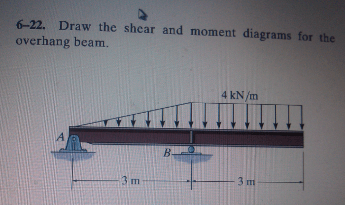
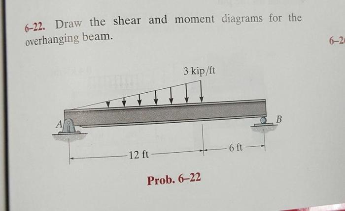
Draw the shear and moment diagrams for the overhanging beam – Drawing shear and moment diagrams for overhanging beams is a fundamental skill in structural analysis, providing valuable insights into the internal forces acting on the beam. This guide will delve into the concepts of shear force and bending moment, exploring how they are influenced by beam properties and loading conditions.
By understanding these diagrams, engineers can assess the structural integrity of overhanging beams and ensure their safe and efficient performance.
Introduction

Shear and moment diagrams are graphical representations that provide valuable insights into the internal forces and stresses within a beam. For an overhanging beam, these diagrams are essential for understanding its structural behavior under various loading conditions.
Shear force is the internal force that acts perpendicular to the beam’s longitudinal axis, while bending moment is the internal force that causes the beam to bend.
Beam Properties

The properties of the beam, such as its length, cross-sectional shape, and material, influence the shear and moment diagrams. A longer beam experiences higher shear and moment forces compared to a shorter beam. Similarly, a beam with a larger cross-sectional area can withstand higher forces than a beam with a smaller cross-sectional area.
Loading Conditions

The type, magnitude, and location of loads applied to the beam affect the shear and moment diagrams. Concentrated loads, such as point loads or moments, create localized peaks in the diagrams, while distributed loads, such as uniformly distributed loads, result in more gradual variations.
Shear Force Diagram, Draw the shear and moment diagrams for the overhanging beam
To calculate the shear force at a given point along the beam:
- Start from one end of the beam and work your way towards the other end.
- Sum up all the vertical forces acting on the beam up to that point, including the reaction forces at the supports and the applied loads.
- The resulting value is the shear force at that point.
The shear force diagram shows the variation of shear force along the beam’s length. It can help identify points of zero shear, where the beam is not subjected to any shear force.
Moment Diagram
To calculate the bending moment at a given point along the beam:
- Start from one end of the beam and work your way towards the other end.
- Sum up all the moments acting on the beam up to that point, including the moments due to the reaction forces at the supports and the applied loads.
- The resulting value is the bending moment at that point.
The moment diagram shows the variation of bending moment along the beam’s length. It can help identify points of zero moment, where the beam is not subjected to any bending moment.
Combined Shear and Moment Diagram
Combining the shear force and moment diagrams into a single diagram provides a comprehensive view of the beam’s internal forces.
By analyzing the combined diagram, engineers can determine the critical sections of the beam where the maximum shear force and bending moment occur. This information is crucial for designing the beam to withstand the applied loads safely and efficiently.
Helpful Answers: Draw The Shear And Moment Diagrams For The Overhanging Beam
What is the purpose of a shear force diagram?
A shear force diagram represents the distribution of shear forces along the beam’s length, indicating the tendency of the beam to resist transverse deformation.
How does the magnitude of the applied load affect the shear and moment diagrams?
The magnitude of the applied load directly influences the values of shear force and bending moment at different points along the beam.
What is the significance of points of zero shear and zero moment in the diagrams?
Points of zero shear indicate locations where the shear force changes direction, while points of zero moment represent locations where the bending moment is zero.